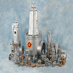


ANS Việt Nam cam kết luôn cung cấp cho Quý khách hàng những sản phẩm và dịch vụ tốt nhất trong các lĩnh vực:
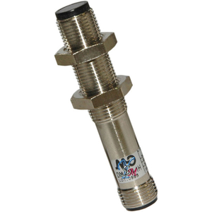
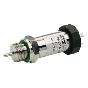
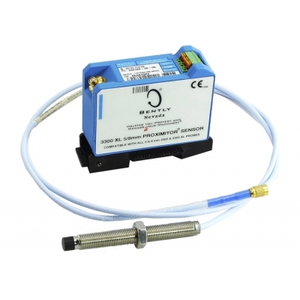
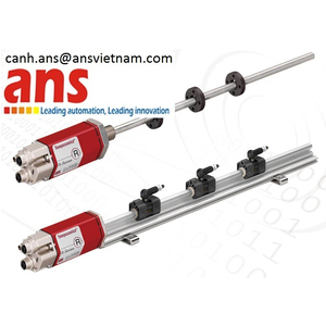
· Factory Automation: cung cấp tất cả dòng sensor như pressure sensors, capacitive sensors, ultrasonic sensors, inductive sensors, photo sensors, magnetic sensors...
· Motion Control: motor, controller, inverter, PLC, encoder, bearing...
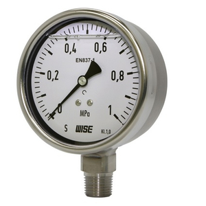
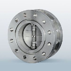
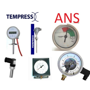
· Process Instrument: các giải pháp về nhiệt – temperature, pressure, level, flow, valves, gauge...
· Electric Part: power cable, control cable, anti-fire cable...
· Safety: relays, switches, fuse...
Với những thương hiệu hàng đầu và uy tín trên khắp thế giới như: Balluff, Wise, Brooks Instrument, Crouzet - Crydom, Kuebler, Ametek, Dakota, Epluse, Koganei, Status, Sterilair,...
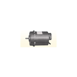
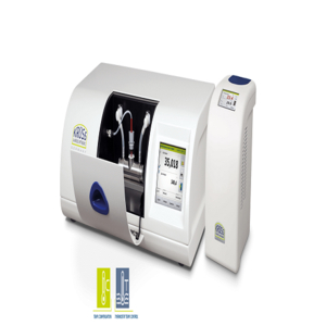
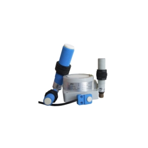
ĐẠI LÝ PHÂN PHỐI CHÍNH THỨC TAKUWA VIETNAM
sản Phẩm của TAKUWA vietnam
| Pressure type Water Level Gauge | |||||
| Discription | Model | Specification | Unit | Remarks | |
| Sensor: select depend on measuring range | |||||
| Pressure Sensor | LSCN-04 | 4m range | Unit | ||
| Pressure Sensor | LSCN-10 | 10m range | Unit | ||
| Pressure Sensor | LSCN-20 | 20m range | Unit | ||
| Sensor Cable | |||||
| Sensor Cable | LSCN-PPC-S | Including wire and air pipe,Max.100m | m | ||
| Junction Box | |||||
| Junction Box | JBCN-1A | Wall-mount, Arrester, Air filter | Unit | ||
| Junction Box | JBCN-10A | Wall-mount, Arrester | Unit | ||
| Signal Coder | |||||
| Signal Coder (Main Unit) | PCCN-AI- [A][B][C] | Unit | |||
| Option | |||||
| A=Analog output | 0= none | ||||
| A=Analog output | 1= 4 to 20mA x 1 | ||||
| A=Analog output | 2= 1 to 5Vx1 | ||||
| B=BCD output | 0= none | ||||
| B=BCD output | 1= BCD x 1 | ||||
| C=Power Source | D= DC12V | ||||
| C=Power Source | A= AC90 to 220V | ||||
| Microwave type Water Level Gauge | |||||
| Discription | Model | Specification | Unit | Remarks | |
| Sensor | |||||
| Microwave Sensor | LSRN-1 | unit | |||
| Junction Box | |||||
| Junction Box | JBRN-1A | Wall-mount, Arrester | unit | ||
| Signal Coder | |||||
| Signal Coder (Main Unit) | PCRN-AR- [A][B][C] | unit | |||
| Option | |||||
| [A]=Analog output | 0= none | ||||
| [A]=Analog output | 1= 4 to 20mA x 1 | ||||
| [A]=Analog output | 2= 1 to 5V x 1 | ||||
| [B]=BCD output | 0= none | ||||
| [B]=BCD output | 1= BCD x 1 | ||||
| [C]=Power Source | D= DC12V | ||||
| [C]=Power Source | A= AC90 to 220V | ||||
| Floating type Water Level Gauge | |||||
| Discription | Model | Specification | Unit | Remarks | |
| Sensor | |||||
| Sensor (Main unit) | LSFL [A][B][C]-[D][E][F] | unit | |||
| Option | |||||
| A= Analog Indicator | 0= none | ||||
| 1= 1 needle | |||||
| 2= 2 needles | |||||
| B= A/D Converter | 0= none | ||||
| 1= 3 disits + Arrester | |||||
| 2= 4 disits + Arrester | |||||
| C= Synchro Transmitter | 0= none | ||||
| 1= type 86 x 1unit | |||||
| 2= type 86 x 2units | |||||
| 3= type 86 x 3units | |||||
| 4= type 23TX x 2units | |||||
| D= Potentio | 0= none | ||||
| 1= Potentio | |||||
| 2= R/I unit + Arrester | |||||
| E= Limit Switch | 0= none | ||||
| 1= 4 points | |||||
| 2= 8 points | |||||
| 3= 4 points + 8 points | |||||
| F= Power Source | 0= none | ||||
| 1=100V 50/60Hz | |||||
| 2=110V 60Hz | |||||
| 3=200V 50/60Hz | |||||
| 4=220V 60Hz | |||||
| 5=DC24V | |||||
| Color Staff Gauges | |||||
| Discription | Model | Specification | Unit | Remarks | |
| Staff Gauge | SG-A | 120W×1000H×2t, Aluminium | piece | Color: Selectable White, Yellow, Red, Green, Orange | |
| Staff Gauge | SG-A150 | 150W×1000H×2t, Aluminium | piece | ||
| Staff Gauge | SG-A200 | 200W×1000H×2t, Aluminium | piece | ||
| Staff Gauge | SG-A300 | 300W×1000H×2t, Aluminium | piece | ||
| Staff Gauge | SG-A500 | 500W×1000H×2t, Aluminium | piece | ||
| Meter Display Sticker | small | 0 to 9 | piece | ||
| Meter Display Sticker | large | 0 to 9 | piece | ||
| Wire Sensor for debris flow detection | |||||
| Discription | Model | Specification | Unit | Remarks | |
| Wire Sensor | WSCR-12 | m | |||
| Junction Box | JBWS-1A | Wall-mount, Arrester | unit | ||
| Control Box | CDWS-1464-21 | Input 5ch | unit | ||
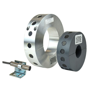
| Vibration Sensor for debris flow detection | |||||
| Discription | Model | Specification | Unit | Remarks | |
| Vibration Sensor | DSVD-04H | unit | |||
| Control Box | DSVD-01C | unit | |||
| Warning device for debris flow | |||||
| Discription | Model | Specification | Unit | Remarks | |
| Main Control unit | DFS-010-01 | unit | |||
| Power Source unit | DFS-010-02 | DC24V | unit | ||
| Rotating Warning Light | RL-02 | unit | |||
| Warning Siren | SU-02 | unit | |||
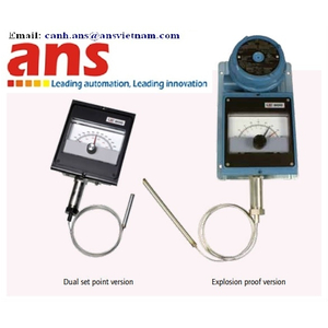
| Shaft-Rotation type Gate Opening Indicator(GISS Series) | |||||
| Discription | Model | Specification | Unit | Remarks | |
| Sensor | |||||
| Sensor (Main unit) | GISS [A][B]-[C][D][E] | unit | |||
| Option | |||||
| A= Analog Indicator | 1= 1 needle | ||||
| A= Analog Indicator | 2= 2 needles | ||||
| B= Limit Switch | 0= none | ||||
| B= Limit Switch | 3= 3 units | ||||
| B= Limit Switch | 6= 6 units | ||||
| CD= Sensor | 00= none | ||||
| CD= Sensor | S1= synchro type 86G x1 | ||||
| CD= Sensor | S2= synchro type 86G x2 | ||||
| CD= Sensor | S3= synchro type 23TX x1 | ||||
| CD= Sensor | S4= synchro type 23TX x2 | ||||
| E= Input shaft | S= One side shaft | ||||
| E= Input shaft | D= Each side shaft | ||||
| Other Option | |||||
| Special Color | except Munsel 7.5BG 6/1.5 | ||||
| Shaft-Rotation type Gate Opening Indicator(GISN210 Series) | |||||
| Discription | Model | Specification | Unit | Remarks | |
| Sensor | |||||
| Sensor (Main unit) | GISN210-86[A] | ||||
| Option | |||||
| A= Externals shape | A : Conduit position: RIGHT.There is a cable connection. | unit | |||
| A= Externals shape | B : Conduit position: LEFT.There is a cable connection. | unit | |||
| A= Externals shape | C : Conduit position: RIGHT.There is a cable no connection. | unit | |||
| A= Externals shape | D : Conduit position: LEFT.There is a cable no connection. | unit | |||
| Shaft-Rotation type Gate Opening Indicator(GISN400 Series) | |||||
| Discription | Model | Specification | Unit | Remarks | |
| Sensor | |||||
| Sensor (Main unit) | GISN40 [A][B]-[C][D][E] | unit | |||
| Option | |||||
| A= Gear construction | G= Normal gear | ||||
| A= Gear construction | L= Backlashless gear | ||||
| B= Gear ratio | Standard ratio | ||||
| B= Gear ratio | Non-standard | ||||
| CD= Included synchronous motor type | 86= 86G | ||||
| CD= Included synchronous motor type | 85= 86DG | ||||
| CD= Included synchronous motor type | 2T= 23TX | ||||
| E= conduit position | A= Right | ||||
| E= conduit position | B= Left | ||||
| Other Option | |||||
| Special Color | except Munsel 7.5BG 6/1.5 | ||||
| Sensor | |||||
| Sensor (Main unit) | GISN40 [A]L-[C][D][E] | unit | |||
| Option | |||||
| A= Gear construction | G= Normal gear | ||||
| A= Gear construction | L= Backlashless gear | ||||
| CD= Included synchronous motor type | 86= 86G | ||||
| CD= Included synchronous motor type | 85= 86DG | ||||
| CD= Included synchronous motor type | 2T= 23TX | ||||
| E= conduit position | A= Right | ||||
| E= conduit position | B= Left | ||||
| Other Option | |||||
| Special Color | except Munsel 7.5BG 6/1.5 | ||||
| Wire-Spring type Gate Opening Indicator(GIWS Series) | |||||
| Discription | Model | Specification | Unit | Remarks | |
| Sensor | |||||
| Sensor (Main unit) | GIWS [A][B][C]-[D][E][F] | unit | |||
| Option | |||||
| [A]= Analog Indicator | 0= none | ||||
| [A]= Analog Indicator | 1= 1 needle | ||||
| [A]= Analog Indicator | 2= 2 needles | ||||
| [B]= A/D Converter | 0= none | ||||
| [B]= A/D Converter | 1= 3 disits + Arrester | ||||
| [B]= A/D Converter | 2= 4 disits + Arrester | ||||
| [C]= Synchro Transmitter | 0= none | ||||
| [C]= Synchro Transmitter | 1= type 86 x 1unit | ||||
| [C]= Synchro Transmitter | 2= type 86 x 2units | ||||
| [C]= Synchro Transmitter | 3= type 86 x 3units | ||||
| [C]= Synchro Transmitter | 4= type 23TX x 2units | ||||
| [D]= Potentio | 0= none | ||||
| [D]= Potentio | 1= Potentio | ||||
| [D]= Potentio | 2= R/I unit + Arrester | ||||
| [E]= Limit Switch | 0= none | ||||
| [E]= Limit Switch | 1= 4 points | ||||
| [E]= Limit Switch | 2= 8 points | ||||
| [E]= Limit Switch | 3= 4 points + 8 points | ||||
| [F]= Power Source | 0= none | ||||
| [F]= Power Source | 1=100V 50/60Hz | ||||
| [F]= Power Source | 2=110V 60Hz | ||||
| [F]= Power Source | 3=200V 50/60Hz | ||||
| [F]= Power Source | 4=220V 60Hz | ||||
| [F]= Power Source | 5=DC24V | ||||
| Other Option | |||||
| Custom-order scale of indicator | onsite adjustment after the delivery | ||||
| Special Color | except Munsel 7.5BG 6/1.5 | ||||
| Limit Switch Box (GILD Series) | |||||
| Discription | Model | Specification | Unit | Remarks | |
| Sensor | |||||
| Sensor (Main unit) | GILD [A][B]-[C] | unit | |||
| Option | |||||
| A= Limit-switch for Multi-turn cam | 0= none | ||||
| A= Limit-switch for Multi-turn cam | 1= 1 piece | ||||
| A= Limit-switch for Multi-turn cam | 2= 2 piece | ||||
| A= Limit-switch for Multi-turn cam | 3= 3 piece | ||||
| A= Limit-switch for Multi-turn cam | 4= 4 piece | ||||
| B= Limit-switch for Single-turn cam | 1= 1 piece | ||||
| B= Limit-switch for Single-turn cam | 2= 2 piece | ||||
| B= Limit-switch for Single-turn cam | 3= 3 piece | ||||
| C=Input shaft rotation direction | |||||
| C=Input shaft rotation direction | |||||
| Other Option | |||||
| Special Color | except Munsel 7.5BG 6/1.5 | ||||
| Synchro | |||||
| Discription | Model | Specification | Unit | Remarks | |
| 23 Series | |||||
| Synchro type 23(Transmitter) | 23TX6 | unit | |||
| 43 Series | |||||
| Synchro type-43(Transmitter) | 43G1 | for 100-110V | unit | ||
| Synchro type-43(Transmitter) | 43G2 | for 200-220V | unit | ||
| Synchro type-43(Receiver) | 43M1 | for 100-110V | unit | ||
| Synchro type-43(Receiver) | 43M2 | for 200-220V | unit | ||
| Bracket for type-43 | ALA400-00 | L-shape | unit | ||
| 62 Series | |||||
| Synchro type-62(Transmitter) | 62G1 | for 100-110V | unit | ||
| Synchro type-62(Transmitter) | 62G2 | for 200-220V | unit | ||
| Synchro type-62(Receiver) | 62M1 | for 100-110V | unit | ||
| Synchro type-62(Receiver) | 62M2 | for 200-220V | unit | ||
| Bracket for type-62 | ALA600-00 | L-shape | unit | ||
| 86 Series | |||||
| Synchro type-86(Transmitter) | 86G1 | for 100-110V | unit | ||
| Synchro type-86(Transmitter) | 86G2 | for 200-220V | unit | ||
| Synchro type-86(Transmitter) | 86G(110V,50Hz) | for 110V,50Hz | unit | ||
| Synchro type-86(Transmitter) | 86G(220V,50Hz) | for 220V,50Hz | unit | ||
| Synchro type-86(Receiver) | 86M1 | for 100-110V | unit | ||
| Synchro type-86(Receiver) | 86M2 | for 200-220V | unit | ||
| Bracket for type-86 | ALA801-00 | L-shape | unit | ||
| Synchro/Digital Converter for gate opening indicator(CGDSW Series) | |||||
| Discription | Model | Specification | Unit | Remarks | |
| Signal Conveter | CGDSW-S1-20 | Input: Synchro x1 | unit | ||
| Signal Conveter | CGDSW-S2-20 | Input: Synchro x2 | unit | ||
| Signal Conveter | CGDSW-S1-11 | Input: Synchro x1, Contact signal | unit | ||
| Signal Conveter | CGDSW-S2-11 | Input: Synchro x2, Contact signal | unit | ||
| Synchro/Analog Converter for gate opening indicator(CSDC4 Series) | |||||
| Discription | Model | Specification | Unit | Remarks | |
| Synchro/Analog Converter | CSDC4 | linear output | unit | ||
| Synchro/Analog Converter | CSDC4-R | non-linear output | unit | ||
| Synchro/Analog Converter | CSDC SA420-1 | ±0.5%, liner output, AC100V | unit | load resistance= 350 or less | |
| Synchro/Analog Converter | CSDC SA420-3 | ±0.5%, liner output, AC200V | unit | load resistance= 350 or less | |
| Synchro/Analog Converter | CSDC SA420A-1 | ±0.5%, liner output, AC100V | unit | load resistance= 750 or less | |
| Synchro/Analog Converter | CSDC SA420A-3 | ±0.5%, liner output, AC200V | unit | load resistance= 750 or less | |
| Synchro Receiver (SRBA Series) | |||||
| Discription | Model | Specification | Unit | Remarks | |
| SRBA100 Series | |||||
| Synchro Receiver (Main unit) | SRBA100-62[A]-[B] | unit | |||
| Option | |||||
| A=Panel size | 3=110□ | ||||
| A=Panel size | 4=120□ | ||||
| A=Panel size | 5=150□ | ||||
| B= Power Source | 1=100V 50/60Hz | ||||
| B= Power Source | 2=110V 60Hz | ||||
| B= Power Source | 3=200V 50/60Hz | ||||
| B= Power Source | 4=220V 60Hz | ||||